VAIDAR: AI-Driven Hardware-in-the-Loop FPGA Verification
Python-native HIL execution engine for AMD Xilinx Artix-7 FPGA silicon with PyTorch & LLM-driven stimulus synthesis and automated failure triage.
Project Overview
VAIDAR (Verification & Artificial Intelligence for Digital Architecture Runtime) is an automated Hardware-in-the-Loop (HIL) verification execution engine developed as my Final Year BEng Individual Dissertation Project at the University of Brighton.
The project achieved a First Class 91% (A+) and was recognised with The IET Prize 2026 by the Institution of Engineering and Technology.
| Letter | Component | Engineering Role in the System |
|---|---|---|
| V | Verification | Automated HIL assertion testbench & cycle-accurate software golden model |
| AI | Artificial Intelligence | LLM edge-case stimulus synthesis & automated failure triage |
| D | Digital | Register-transfer level (RTL) Verilog logic & control FSM design |
| A | Architecture | 16-bit ALU core synthesised onto AMD Xilinx Artix-7 silicon |
| R | Runtime | Real-time 921,600 baud streaming execution engine (~1,000 tests/sec) |
Traditional FPGA verification relies heavily on manual bench testing with oscilloscopes and function generators, or slow software RTL simulation that can consume up to 70% of the hardware design lifecycle. Inspired by telemetry principles in RADAR and LiDAR systems, VAIDAR bridges physical silicon with modern software testing by wrapping high-speed serial transports in an intuitive Python architecture and integrating LLM-assisted edge-case test generation.
Physical Testbed Setup
The hardware validation platform consists of dual host workstations communicating bidirectionally with Digilent Nexys A7 FPGA boards over a high-speed CP2102 USB-to-UART bridge operating at 921,600 baud:
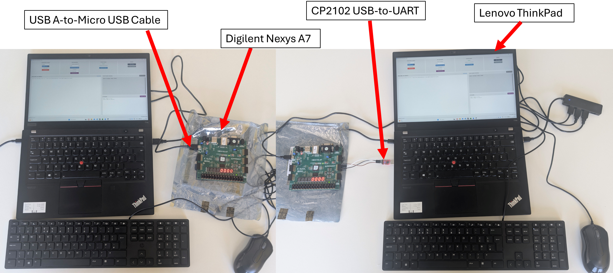 Figure 1: Dual host workstations connected to physical Digilent Nexys A7 FPGA boards via high-speed USB-to-UART bridge.
Key Performance Metrics & Benchmarks
| Metric | Software Simulation | Manual Bench Testing | VAIDAR HIL Framework |
|---|---|---|---|
| Max Throughput | ~20–50 tests/sec | ~1 test/45 sec | 968.9 tests/second |
| 10,000 Test Run Time | ~12–25 minutes | Prohibitive (~125 hrs) | 10.38 seconds |
| Physical Accuracy | Approximate (No Parasitics) | 100% Physical Silicon | 100% Physical Silicon |
| Triage & Diagnosis | Manual waveform inspection | Manual Multimeter/Scope | Automated AI Analysis (Gemini) |
Real-Time Python & AI Automation Suite
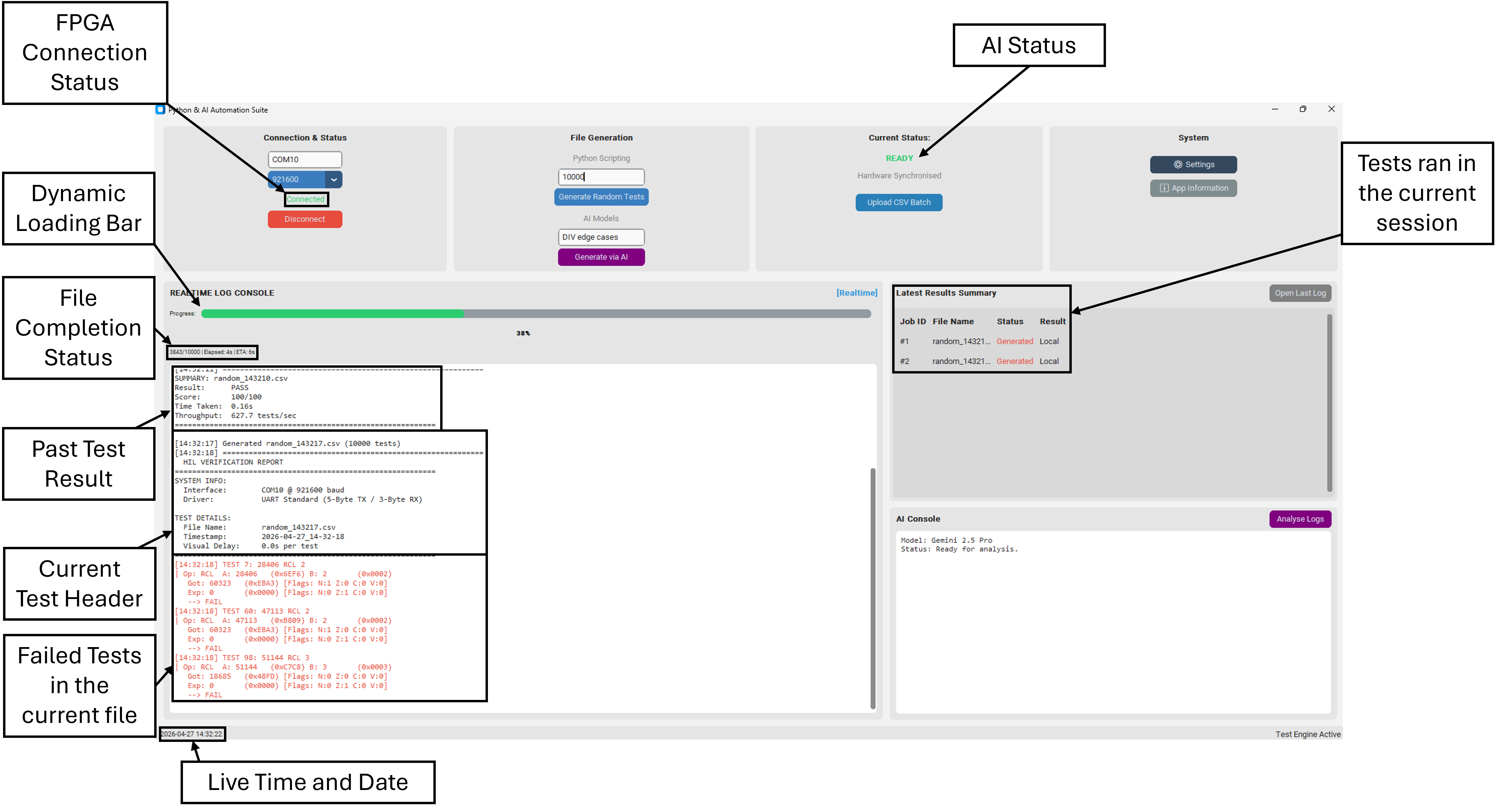
The desktop control application (shown in the header interface overview) provides interactive FPGA connection management, test generation, and live execution logging with automated discrepancy triage.
Hardware & Software Architecture
1. Hardware Silicon: 16-Bit Arithmetic Logic Unit (ALU)
The Device-Under-Test (DUT) is a multi-stage 16-bit Verilog ALU synthesised onto the AMD Xilinx Artix-7 FPGA fabric supporting 18 arithmetic, logical, and memory operations:
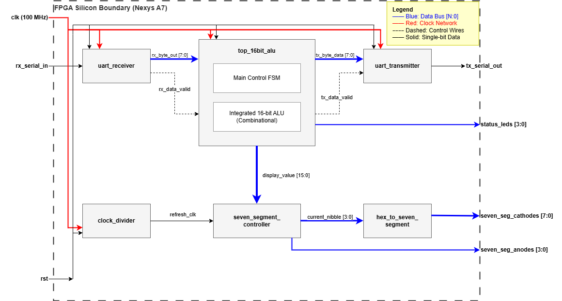 Figure 2: Synthesised 16-bit ALU datapath and internal register bus routing.
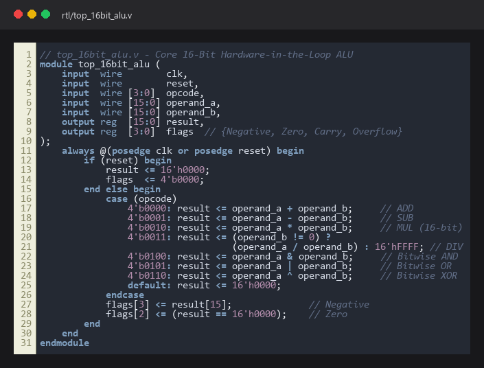 Figure 3: Core Verilog RTL execution process handling 16-bit arithmetic with zero-division bypass and condition flags.
2. Software Architecture: Closed-Loop AI Stimulus Loop
The Python orchestrator incorporates an autonomous stimulus generation and telemetry analysis loop:
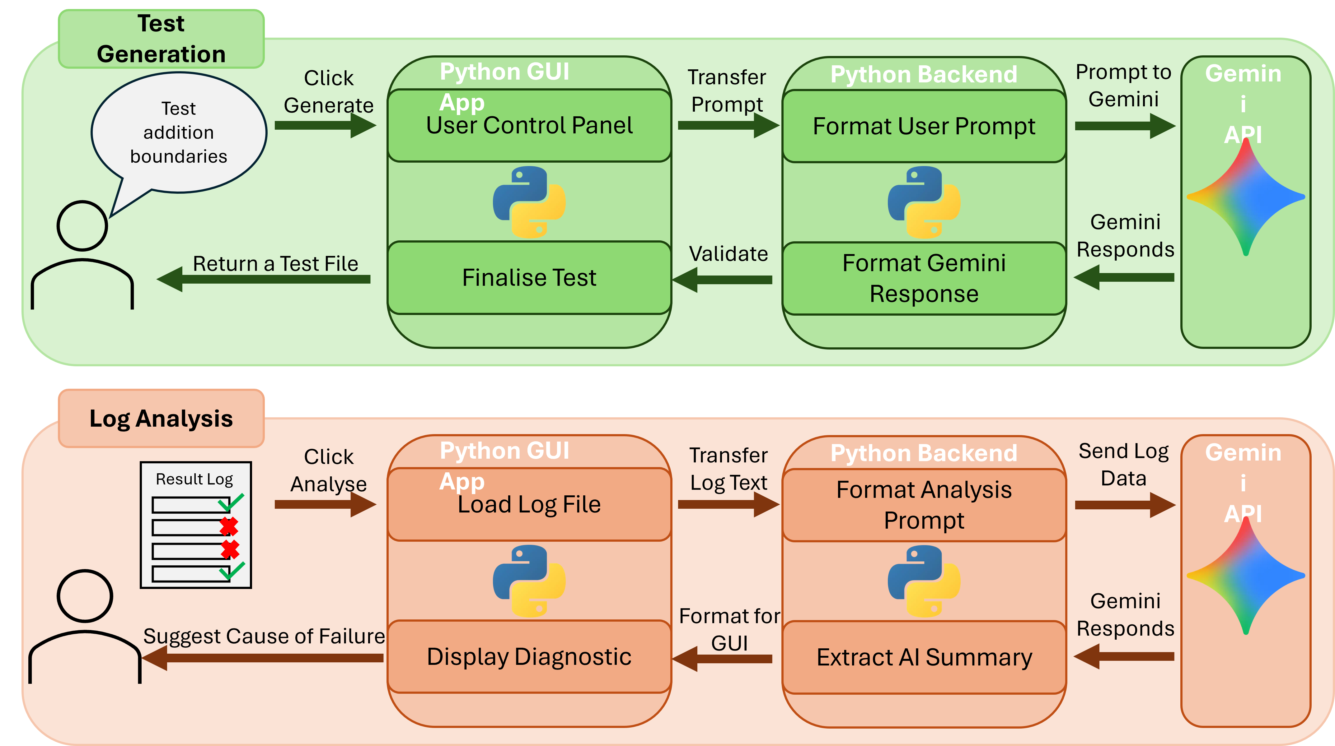 Figure 4: Closed-loop AI integration workflow leveraging LLM APIs for intelligent boundary fuzzing and failure diagnosis.
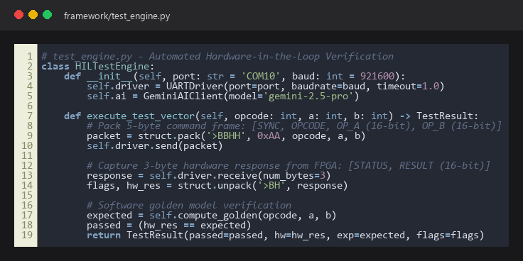 Figure 5: Python HIL engine serialising binary frames and cross-verifying physical FPGA responses against golden models.
Academic Deliverables & Attribution
- GitHub Repository: HarryRogers073/vaidar
- Author: Harry Rogers (University of Brighton)
- Academic Context: Capstone BEng Individual Dissertation Project (First Class 91%, IET Prize Winner 2026)
- Academic Exhibition Poster: Download High-Resolution Vector PDF
- Target Silicon: Digilent Nexys A7 FPGA (AMD Xilinx Artix-7
XC7A100T) - EDA Tools: Xilinx Vivado Design Suite 2024.1, ModelSim-Intel FPGA
- Attribution & Provenance:
- Custom Code & RTL: The Python HIL test execution engine, golden reference model, CustomTkinter desktop interface, 16-bit Verilog ALU, and 7-segment display driver were authored by Harry Rogers.
- Adapted Hardware: The physical UART receiver (
uart_receiver.v) was adapted from Russell Merrick’s Nandland open-source serial receiver module with custom framing logic. - Open-Source Libraries: Makes use of standard Python open-source libraries (
pyserial,customtkinter,matplotlib, and official Google/Anthropic/OpenAI SDKs).