Data Communications & Multi-Site WAN Network Architecture
Hierarchical WAN topology in Cisco Packet Tracer: Layer 3 serial routing (V.35 DTE/DCE), WPA2-PSK wireless infrastructure, IoT automation, and RF Sensing / CSI analysis.
Project Overview
A comprehensive telecommunications systems investigation and network architecture simulation engineered for the Data Communications & Telecommunications curriculum at the University of Brighton (awarded a First Class 90% / A+), taught by Dr. Deshinder Singh Gill.
The project investigates data communications across all seven layers of the OSI model using Cisco Packet Tracer, culminating in the design and critical evaluation of an advanced, multi-layered Wide Area Network (WAN). Beyond standard networking primitives, the research evaluates emerging telecommunications paradigms, specifically the transition from conventional packet-switched data connectivity to RF Sensing and Channel State Information (CSI) analysis using Software-Defined Radios (SDR).
Physical Topology & Hierarchical Architecture
To test protocols under complex routing and physical isolation constraints, a multi-site network architecture was engineered spanning geographically separated locations connected across leased-line serial backbones:
Site Hierarchy & Subnet Partitioning
The architecture partitions network resources between primary and remote operational zones, ensuring strict broadcast domain isolation:
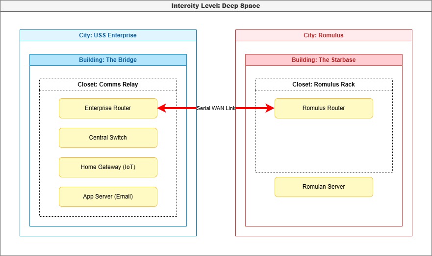 Figure 1: Multi-site topological hierarchy showing localised Local Area Networks (LANs) bridged across wide-area serial routing points.
Key Network Implementations & Protocols
1. Secure Wireless Infrastructure (WPA2-PSK / AES)
Unlike standard open networks, enterprise-grade wireless security was configured on the Gateway router using WPA2-PSK (AES) encryption to protect over-the-air frame transmission from eavesdropping and packet injection:
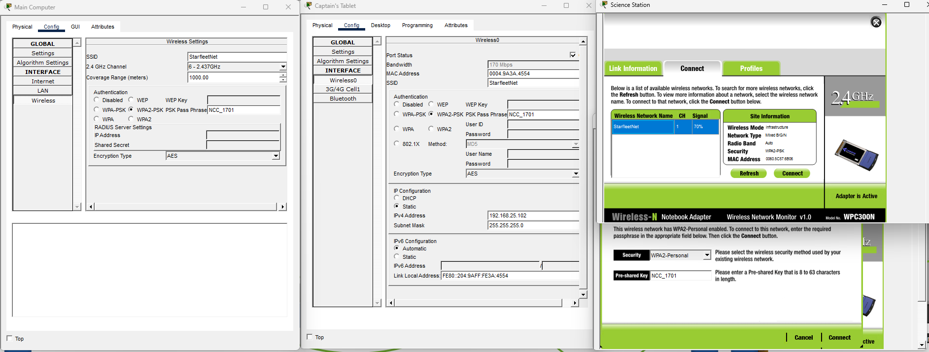 Figure 2: WPA2-PSK (AES) pre-shared key authentication configured on the gateway, serving secured wireless endpoints.
2. Layer 3 Serial WAN Routing (V.35 DTE/DCE)
To simulate a commercial T1 leased line across subnets, a remote Web Server (10.2.0.10) was deployed across a Serial V.35 physical link. The link was configured as a DTE/DCE pair, where the local gateway router acted as Data Circuit-terminating Equipment (DCE) providing clock synchronisation (clock rate 64000), and the remote gateway functioned as Data Terminal Equipment (DTE).
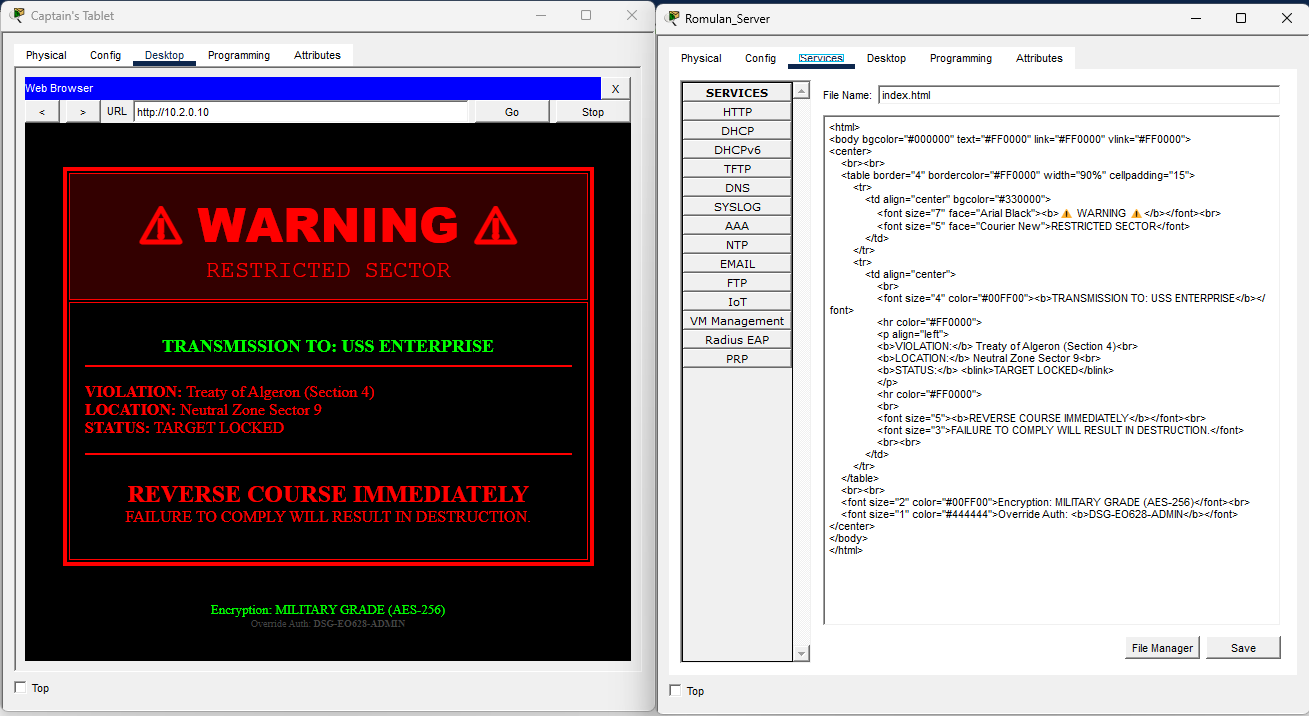 Figure 3: Layer 3 serial routing table and RIP dynamic routing protocol exchange bridging distinct network segments.
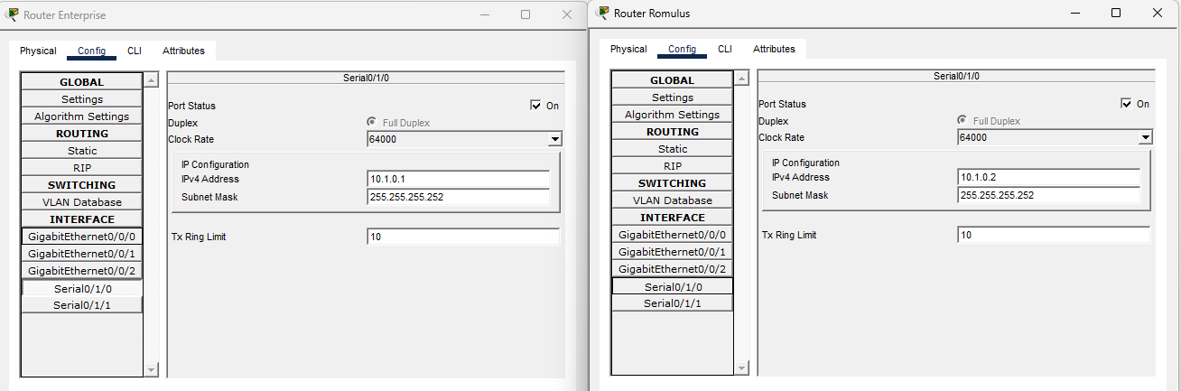 Figure 4: Verification of cross-subnet HTTP packet delivery across the serial link, confirming end-to-end packet delivery.
3. Protocol Data Unit (PDU) & TCP Handshake Analysis
Every stage of network communication was verified using Packet Tracer’s discrete-event simulation engine, capturing TCP 3-way handshakes (SYN, SYN-ACK, ACK), sequence number increments, and ARP table resolution:
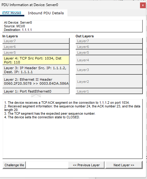 Figure 5: Layer-by-layer PDU header breakdown examining source/destination ports, TCP flags, window sizing, and payload byte offsets.
4. Client-Server Application Services (SMTP / POP3 Email)
Dedicated application layer services were deployed, configuring standalone DNS name resolution and SMTP/POP3 mail transfer agents:
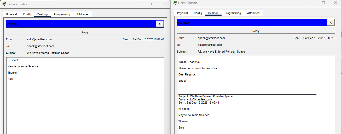 Figure 6: Successful mail transmission between isolated client endpoints across the network.
5. Automated Environmental IoT State Machine
An integrated IoT sub-network was engineered using conditional logic routines on the Gateway controller to respond autonomously to simulated sensor inputs (e.g., automated ventilation actuation based on ambient atmospheric sensor readings):
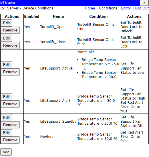 Figure 7: IoT event automation rules evaluating multi-condition sensor inputs to trigger physical actuators.
Advanced Theoretical Evaluation: From Data Connectivity to RF Sensing
A central component of this research is a critical evaluation of simulation fidelity versus physical electromagnetic reality. While simulation tools assume ideal deterministic bit transfers, real-world communications are governed by multipath fading, shadow fading, and electromagnetic interference.
Channel State Information (CSI) & Software-Defined Radio (SDR)
Drawing on cutting-edge research led by Dr. Muhammad Bilal Khan at the University of Brighton, the report critiques how IEEE 802.11 Wi-Fi signals can be repurposed beyond data transport for RF Sensing:
- Physical Wave Perturbation: As radio frequency waves propagate through an environment, physical obstacles and human movements induce minute scattering, diffraction, and Doppler shifts.
- CSI Extraction: Whereas received signal strength indicators (RSSI) provide only coarse power amplitude, Channel State Information captures fine-grained phase and amplitude matrices across individual OFDM subcarriers.
- SDR Integration: Using Software-Defined Radios (such as USRP or HackRF), physical perturbations in CSI matrices can be classified via machine learning algorithms for human presence detection, respiration tracking, and non-line-of-sight gesture recognition without physical cameras or sensors.
Panopto Video Walkthroughs
The network design, protocol configurations, and live packet simulations were recorded and presented as part of the academic submission:
- Module 1 (Getting Started): Watch Panopto Recording
- Module 2 (Exploring Networking & Routing): Watch Panopto Recording
- Module 3 (IoT Automation & Logic): Watch Panopto Recording
- Final Custom Architecture (WAN & Starship Topology): Watch Panopto Recording
Technical Summary & Academic Integrity
- Curriculum: Data Communications & Telecommunications, University of Brighton
- Faculty Supervisor: Dr. Deshinder Singh Gill
- Author: Harry Rogers
- Tools: Cisco Packet Tracer, Wireshark, IEEE 802.11 / 802.3 Protocol Stacks
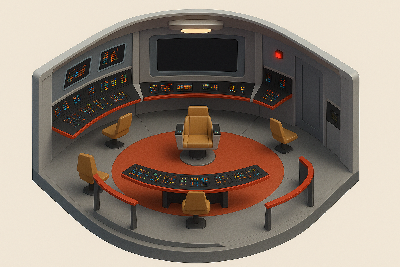
- Academic Disclosure: Topology diagrams, routing configurations, IoT conditional state logic, and report evaluation authored by Harry Rogers. The physical workspace background image was generated with generative AI assistance as disclosed in Appendix 7.1 of the submission report.